> For the complete documentation index, see [llms.txt](https://docs.lightact.com/llms.txt). Markdown versions of documentation pages are available by appending `.md` to page URLs; this page is available as [Markdown](https://docs.lightact.com/projection-mapping/iris/adding-and-calibrating-iris-camera.md).
# Adding and manually calibrating Iris camera
Adding an Iris camera to the viewport and calibrating it with a manual approach.
## Adding a camera to the Viewport
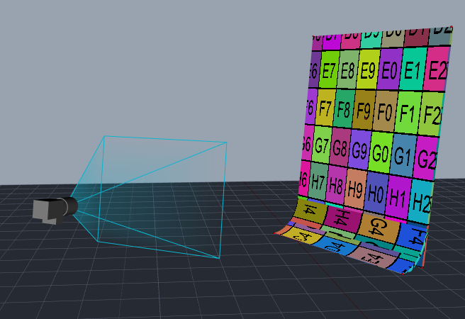
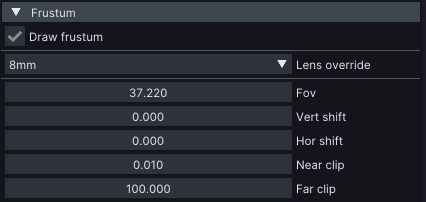
Insert an Iris camera and place it roughly where its physical counterpart is relative to the projection object. You also might want to adjust its frustum, so that it corresponds to the FOV of the physical camera.
The easiest way to is to use **Lens override** dropdown.
## Mapping Iris camera
Before we can proceed to calibrating Iris camera, we need to map it to Iris device node and to the projection objects.
### Mapping Iris camera to Iris device node
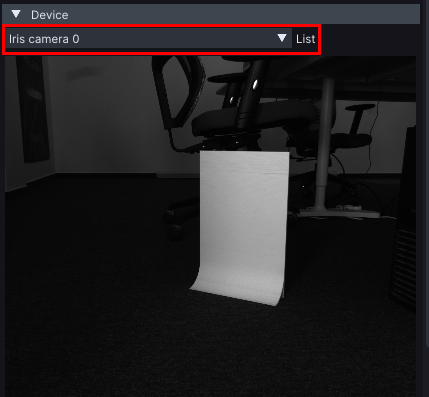
Select Iris camera in Viewport. In its properties on the right, in **Device** section, select **Iris device node** you created in previous chapter.
{% hint style="info" %}
**Good to know:** Mapping *Iris camera* in the Viewport to an *Iris device* node tells Iris camera which physical Iris camera it should get its image from.
{% endhint %}
### Mapping projection objects to Iris camera
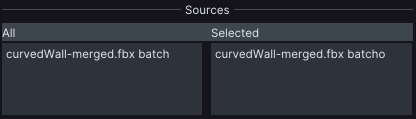
Mapping of projection objects to Iris camera in the Viewport is done either by dragging from projection object to the camera or by using the camera's **Sources** properties.
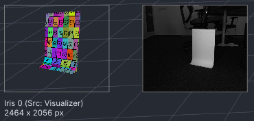
Once this is done, the camera should see theprojection object in the *Viewport* and the image of the virtual object should appear when you select the camera.
## Calibrating a camera
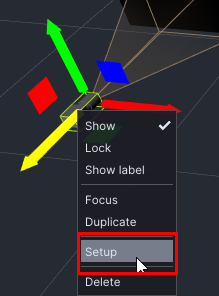
To calibrate Iris camera, just double click on the camera in the viewport or right click on it and select **Setup**.
Iris’ 3DCal window will open and the process of calibrating the camera is more or less the same as the process of calibrating a projector. Therefore, we won’t go into the details here, but please refer to **3DCal chapter***:*
{% content-ref url="/pages/ocMISLUm5TLibi37zOs0" %}
[3DCal](/projection-mapping/3d-projection-mapping-workflow/3dcal.md)
{% endcontent-ref %}
The only difference between the 2 windows are these.
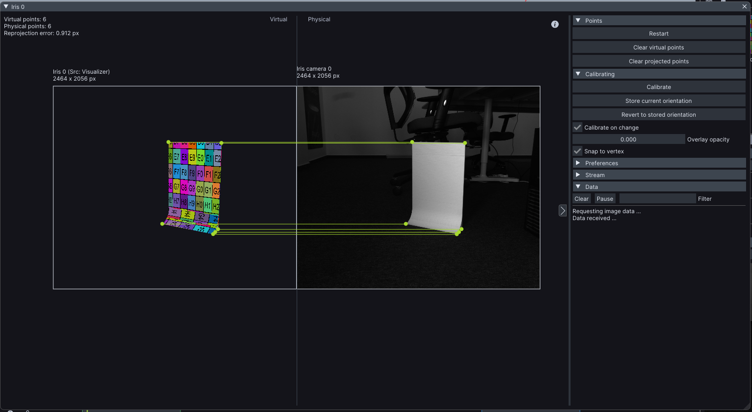
* In the 3DCal window of the projector, you select **Projected points** on the right hand side. In the camera’s window, you select **Physical points** and you click on the camera’s image itself (as opposed to clicking on the cursor on the projected object).
* Camera’s 3DCal window has *Stream* section in the properties, where you can adjust the settings of the device node.
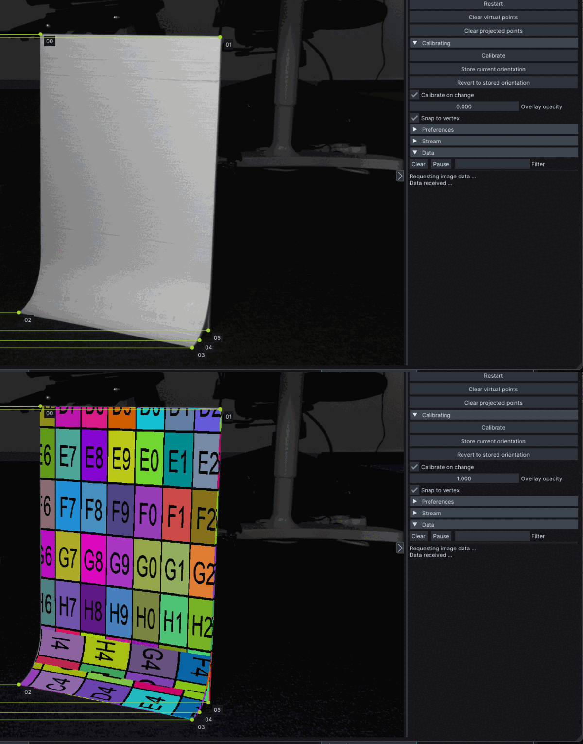
* It also has *Overlay opacity* which is very helpful in order to visually judge the precision of the calibration process.
After you’ve selected 6 or more points camera will get calibrated. Below you will see an example of a good calibration of the camera.
You can see, the reprojection error is below 1px and the yellow calibration lines are all parallel.
Another useful indicator of a good calibration, is changing the **Overlay opacity** (you can use shortcut ‘O’). If, when changing the *Overlay opacity*, the visual and physical image don’t change much, it means that the virtual camera is precisely where the physical camera is in relation to the projection object.